BASIC WIRED COMMUNICATION WITH TWO ARDUINOS
 ||||||||||
||||||||||
||||||||||
Can two arduinos exchange data?
Digital communication refers to the transmission of data, information, and messages through digital devices and channels. With the increasing reliance on technology and the Internet, digital communication has become a crucial aspect of modern society. In order for this to work a common framework is needed. In this laboration you will set up a basic communication protocoll between two Arduinos.
- TX_LED code.png (750 Downloads)
- ASCII table.png (807 Downloads)
- TX_LCD code.PNG (768 Downloads)
- RX_LCD code.PNG (780 Downloads)
- RX_LCD_clock code.PNG (749 Downloads)
- TX_LCD_clock code.PNG (731 Downloads)
Additional Info
-
What you will learn:
- Math:
- - Calculation in transmission speed.
- Engineering:
- - Some basic electronic. Understand code
- Technology:
- - Basic knowlage in how electronic devices communicate between eachother.
-
Expected Time:
Less than 5h
-
Materials & Recycled Materials:
- - 2x Arduino board (e.g. Arduino Uno)
- - 4x LEDS
- - Dupont Cables
- - 2x LCD displays
- - 2x 220Ω resistor
- - 2x 1kΩ resistor
- - 2x 100 kΩ Potentiometer
- - breadbords
- - Oscilloscope (not mandatory but will help with visualisation)
-
Guide:
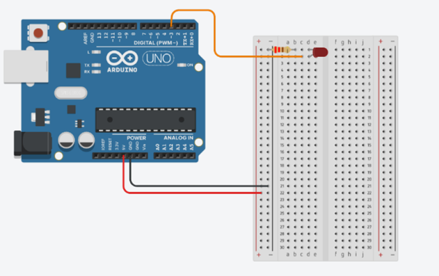
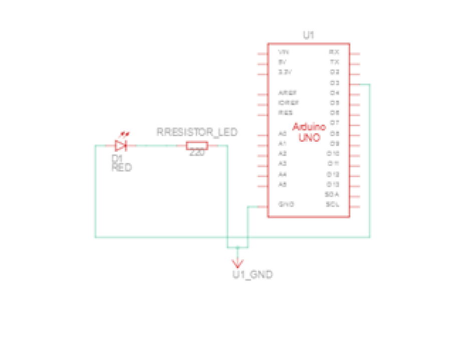
- Step 1: Connect a led to arduino and use ascii table
-
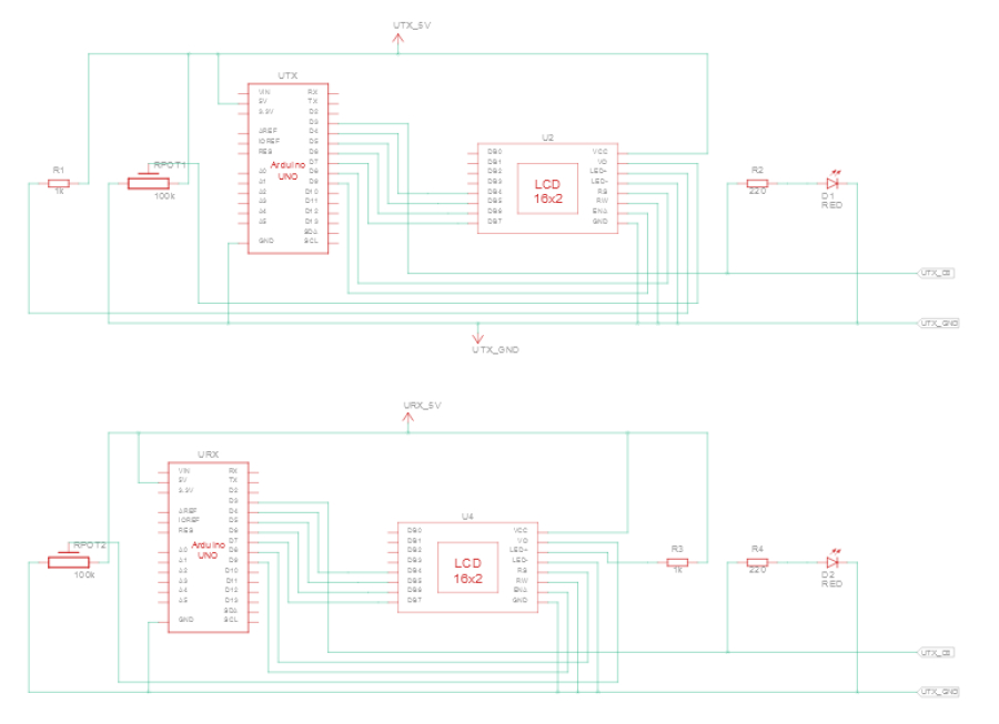
Follow this circuit diagram:


-
When you have done that, you need to write the code. The code will in this stage only be for the transmitter. You will find the code in TX_LED code. The program will now work in such a way that every time the signal is high the LED will light up and when its low it will turn off. The combination of high and low will be dependent of what character you are sending. This is done by the computer using something that is called an ASCII table. In this table all English characters are represented. The message you will send is “Hello, world!” And if you look in the ASCII table, see ASCII table you will see that capital H will correspond to the binary sequence of 01001000.
If you have an oscilloscope now would be a good time to connect it to the circuit to see the signal and how it behaves.
-
Question: What is the bit combination for sending “!”?
-
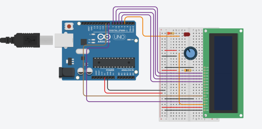
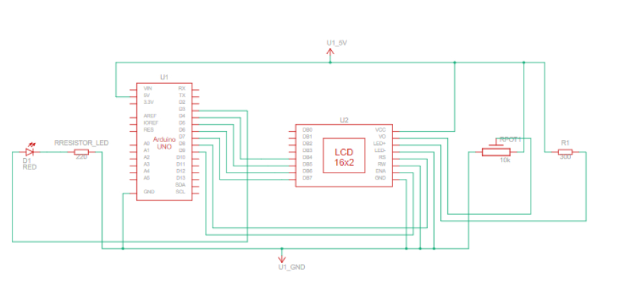
Step 2: Connect the LCD
-
Because it will be easier to visualize the transmission you will add the LCD display to your set up.


-
One thing that is important is not to mix up the connection between ground and voltage. If you do that you will likely damage the screen. The code in Tx_LCD code will probably contain things that you haven’t used before when you programmed. Not to worry if you understand the code in every detail the important is that you understand the basic of what happens in the code If everything works at this stage the LCD will show the message and beneath it the corresponding binary sequence will show. For the moment you are now done with the transmitter
-
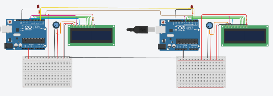
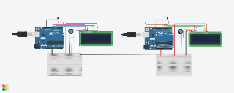
Step 3: Build the receiver.
-
At this point you have only built the transmitter, but to actually transmit something, you need to build a receiver. The circuit for this is just an exact copy of the transmitter. The new thing that needs to be added to the circuit is the communication cables. One cable will be for the transmission the other one will be connected to ground between the Arduino’s.
For the code see RX_LCD code. 

-
-
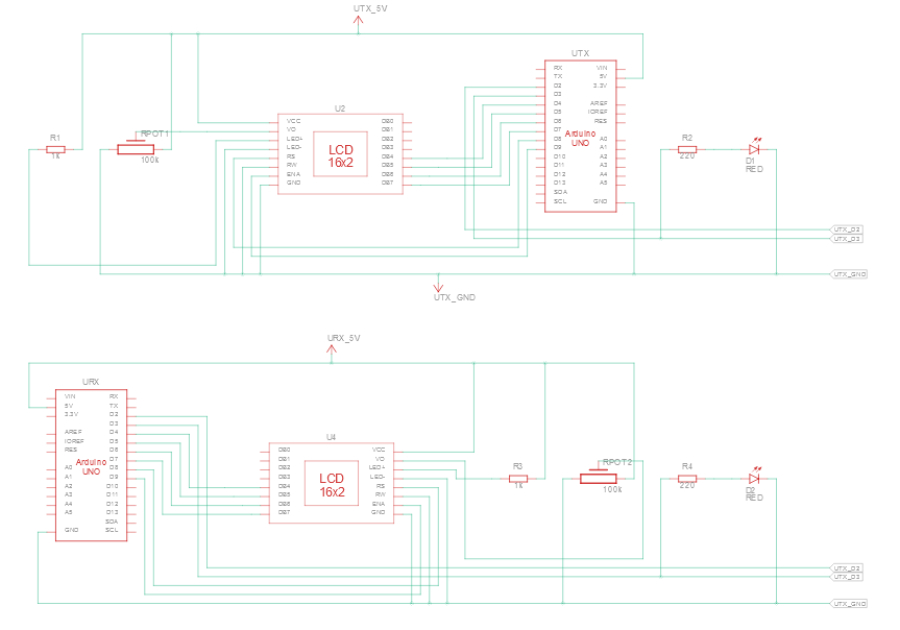
Step 4: more reliable transmission
-
It was possible to send something, but the transmission would probably get scrambled quickly so you just ended up sending gibberish. There are several ways to solve the problem. One is to tweak the bitrate. But in our case that is not a good solution because that will just end up delaying the problem if you send something else. The most common way to solve the problem with a stable communication is to send with a common clock signal, and this is how you are going to solve this too.
First you need to add some code to your transmitter side see TX_LCD_clock code. The big change comes to the receiver side. See RX_LCD_clock code. The main change to the code is that the receiver will only start to listen when the transmitter starts to send. This is achieved by using something called interrupt. The last thing you ned to add is one extra wire. This is for the common clock. The clock signal will be from the sending side and will be like a metronome for the transmission. 

-
Further Steps:
If you want more fun you can:
- - Error detection and error corection in digital communication
-
Software used in the project:
- - Arduino IDE
- Difficulty level: Hard
- Developed By: GTC - SW
Media
No media available for this project
WARNING! If you add a comment you accept the privacy policy!