
 ||||||||||||||
||||||||||||||
||||||||||||||
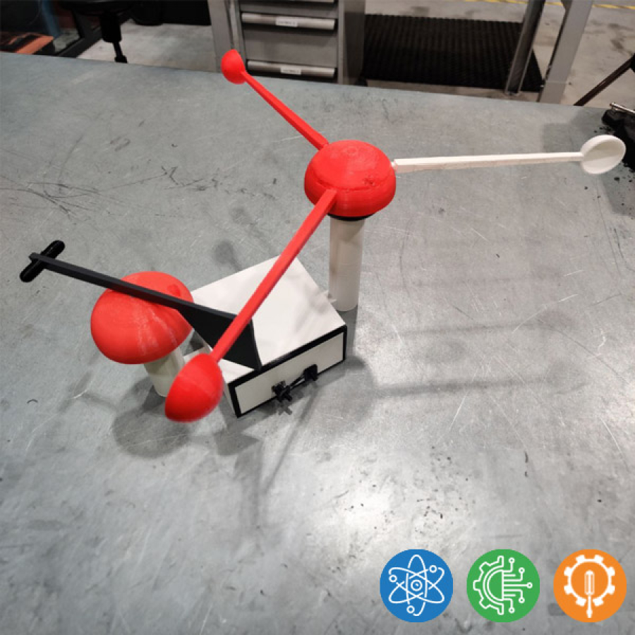
How fast is the wind?
Design and build a 3D-printed windmeter
Download attachments:
- Circuit pictures and code.pdf (714 Downloads)
Additional Info
-
What you will learn:
-
Science: The student learns about windmeasuring
-
Engineering: Mechanical engineering, programming
-
Technology: 3D-modelling and printing, basic electricity and electronics.
-
-
Expected Time:
120h
-
Materials & Recycled Materials:
- Arduino Uno
- 4 pcs IrDa transceiver (TCRT1000 or similar)
- Unipolar Hall sensor
- Neodym magnet 5x5 mm
- I2C-compatible 16x2 LCD-screen
- 2 pcs ball bearings 35x15x12 mm
-
Guide:
- Read the guide while looking at the given pictures. Design the 3D-printable parts according with the guide requirements and personal style.
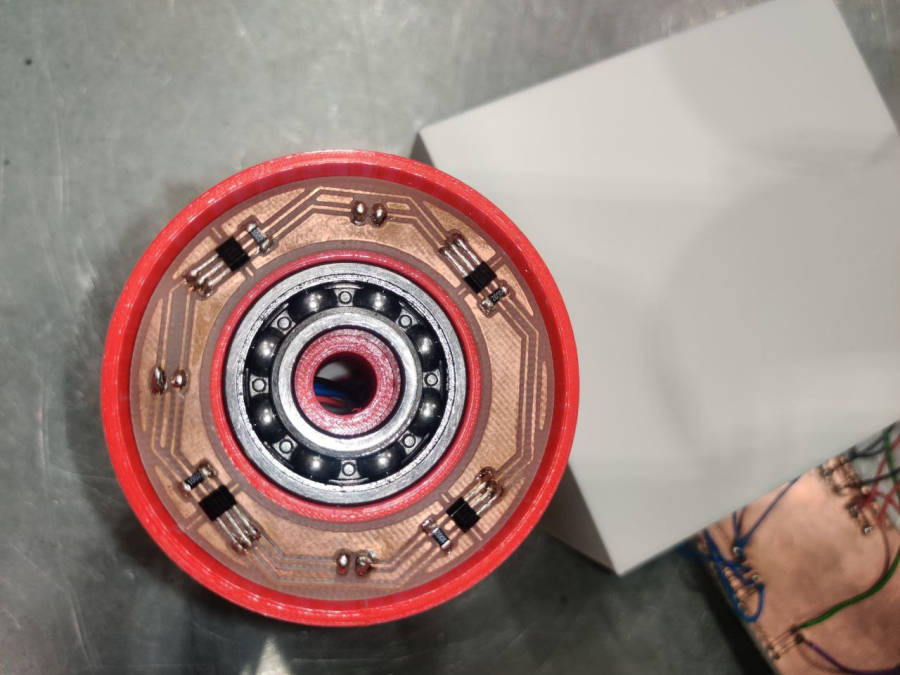
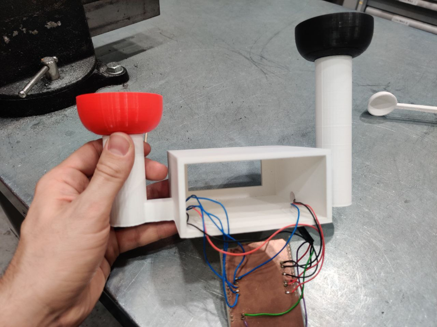
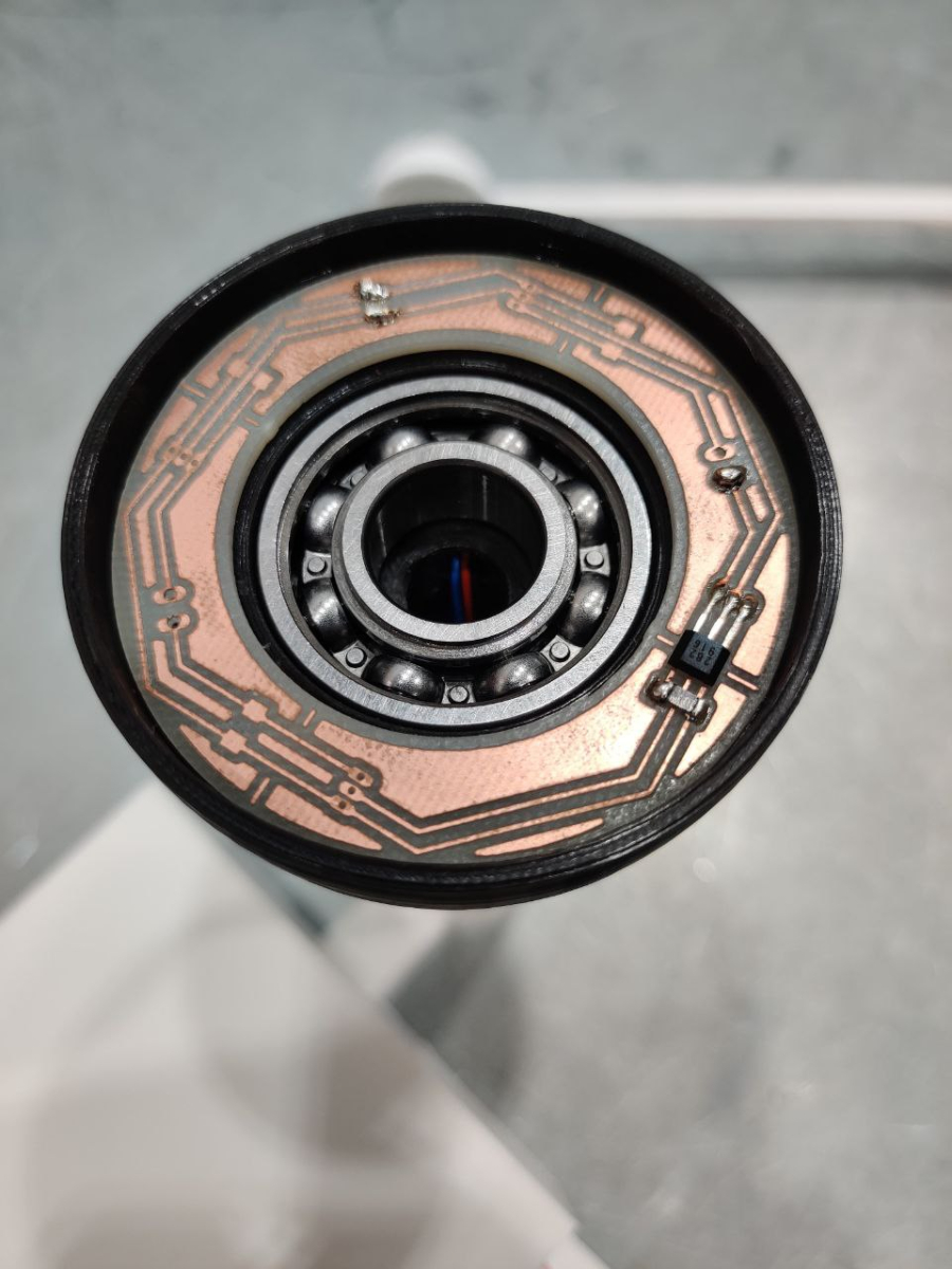
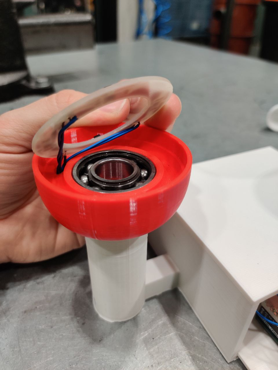
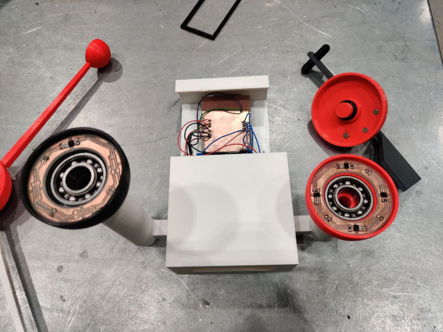
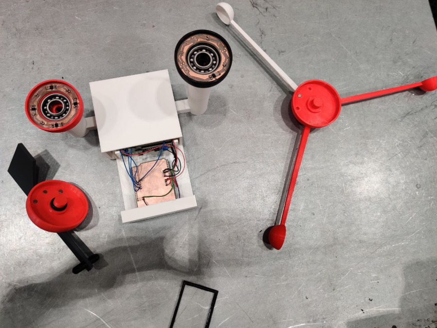
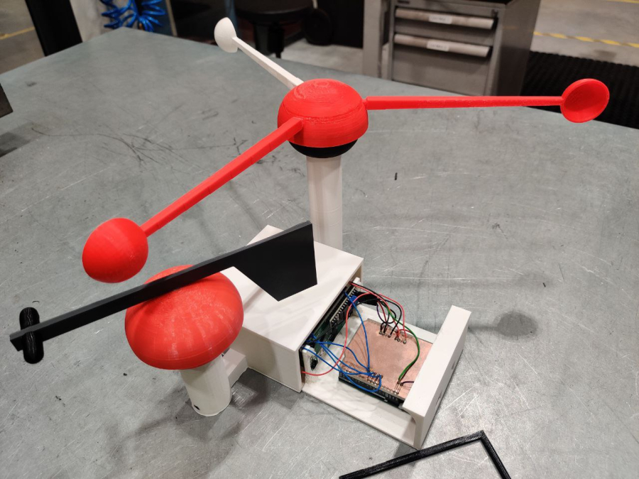
- Speed sensor: in the speed sensor the magnet activates the Hall-sensor when the last one is bypassed. The sensor must be of unipolar type and the magnet has to be correctly assembled. 34-40 cm long wires are soldered to the circuit board. Sensor’s circuit board and bearing are placed lower 3D-printed part. Magnet and windmeter spoons are attached to the upper 3D-printed part. Lower part is connected to the Arduino’s case by a 3D-printed pipe.
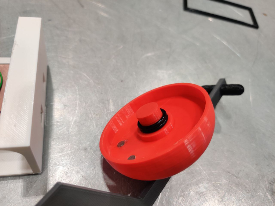
- Direction sensor: IR-receptors react to the 3D-printed top part’s reflected light. There is a IR-Led and a IR-transistor in the sensor. 30-40 cm long wires are soldered to the circuit board. Sensor’s circuit board and bearing are placed in the 3D-printed lower part. Upper part is non-reflective material and a 140 ° wide surface is fixed to it. The 3D-printed direction arrow is attached to the upper part. Lower part is connected to the Arduino Uno’s case via 3D-printed pipe.
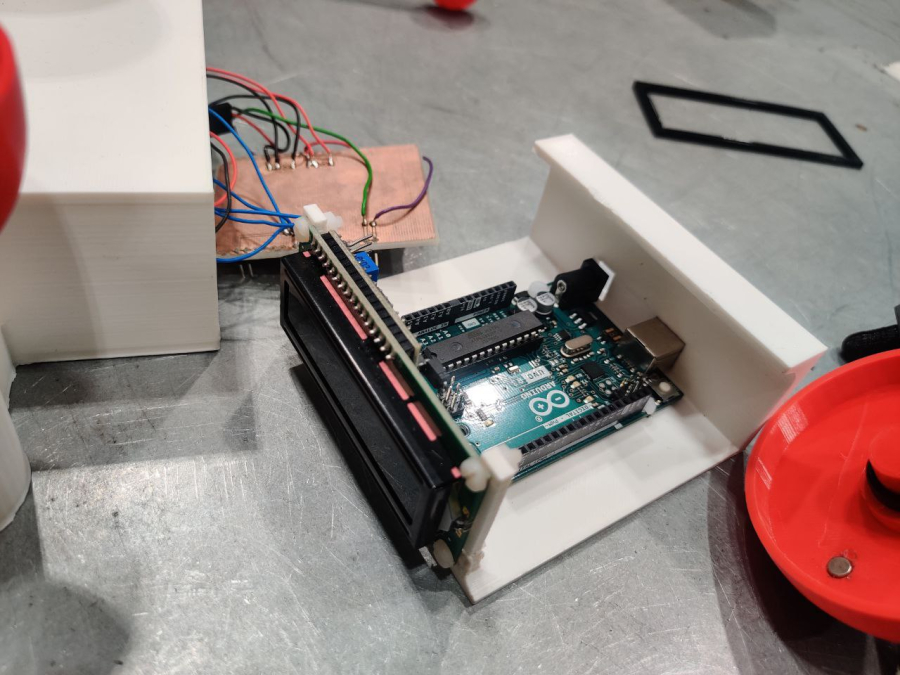
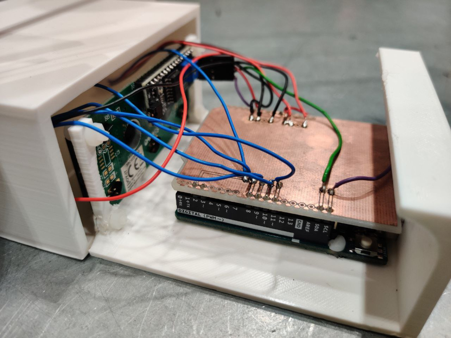
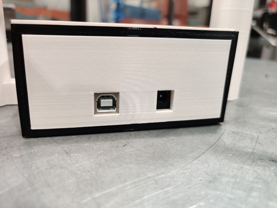
- Arduino’s case: 3D-modeled case is 3D-printed for the Arduino and the LCD-display. A circuit board is designed to Arduino’s top, where sensor’s wires and LCD-display are connected.
- Programming: Speed sensor is read with a stop and sensor is to be connected to Arduino’s inputs D2 or D3. Direction is read at digital inputs and sensor is connected to Arduino inputs D8-D11. LCD-display is driven via I2C pins and display is connected to connectors SDA and SCL.
-
Further Steps:
- Once the assembly works, try modeling and building a second one with different style or size.
-
Software used in the project:
- - Solidworks
- - Ultimaker Cura
- - Eagle.
- Difficulty level: Hard
- Developed By: Salpaus
Media
No media available for this project
WARNING! If you add a comment you accept the privacy policy!